|
Data Source Definition Wizard |
The Data Source Definition Wizard provides a simple six-step process that, when completed, creates a new data source definition. See Data Source Definition Wizard Steps.
From the data source definition, views can be created to display only selected data. The data source definition can be recalled in Data Source Maintenance and updated as needed.
(The Data Source Definition Wizard was added in PxPlus 2021.)
To invoke the Data Source Definition Wizard, use one of the following methods:
|
Location |
Method |
|
From the PxPlus IDE Main Launcher |
Expand the Views category. Select Data Source Wizard. |
|
Click the New Data Source tool bar button. |
Specify the type and name of the primary data source to be accessed.
Define the elements (columns) to include in the data source.
Define any relationship(s) between the primary data source and its related data sources.
Specify logic to be performed in the data source definition.
Assign the data source definition to an existing group.
Complete the Data Source Definition Wizard and save the data source definition. Before completion, review selections for previous steps and make any necessary changes.
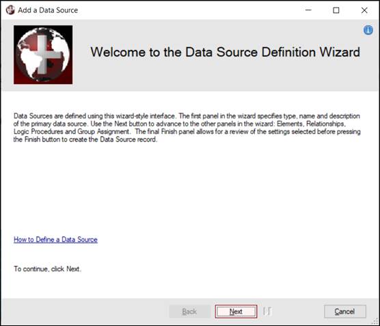
The Welcome panel provides general information about the Data Source Definition Wizard and includes a How to Define a Data Source link that launches PxPlus Help documentation.
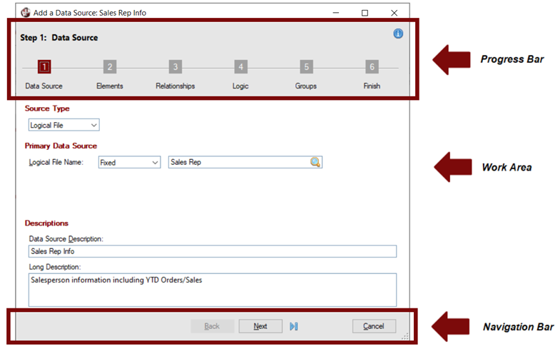
Click Next to proceed to the first step. Each step in the wizard presents a panel made up of three main sections:
These sections are explained below.
|
Progress Bar |
Displays the six steps for defining a data source. A white step number against a dark red background indicates the current step being defined. Clicking on a step number goes directly to that step without having to select intermediate steps in order. This is useful when reviewing or changing previous selections before exiting the wizard. Keep in mind that certain steps may require data before advancing to subsequent steps. | ||||||||||||
|
Work Area |
Body of the wizard panel and consists of fields used to process each step. | ||||||||||||
|
Navigation Bar |
Consists of buttons that are shown/hidden or enabled/disabled, depending on the step being defined:
|
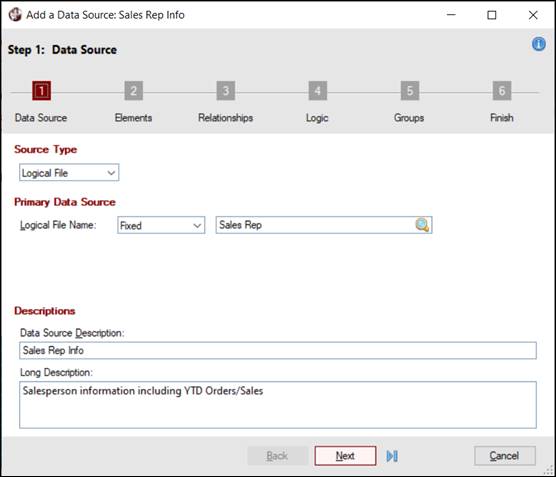
Specify the type and name of the primary data source to be accessed. Enter a description to identify the data source being defined.
This panel consists of the following:
|
Source Type |
Specify the type of data source to be accessed. Generally, a data source is a file or table but can also be a PxPlus object that adheres to a pre-defined interface standard. See Custom Data Source Objects. Native PxPlus data files must contain embedded data dictionaries and can be identified by Logical Table Name or by physical path name. The Views System can also access external databases (e.g. ODBC, ADO, MySQL, Oracle and DB2). All data sources must have key definitions. | ||||||||||||||||||||||||||||
|
(Source Type Drop Box) |
Click the drop-down arrow for a list of source types: Logical File, Physical File, Data Base Table, Source Object. | ||||||||||||||||||||||||||||
|
Primary Data Source |
(Required) Specify the primary data source containing the data to be accessed. | ||||||||||||||||||||||||||||
|
The fields displayed will vary depending on the Source Type selected:
Note: | |||||||||||||||||||||||||||||
|
Descriptions |
Specify descriptions to identify the data source. | ||||||||||||||||||||||||||||
|
Data Source Description |
Displays a default (depending on the Primary Data Source entered), which can be replaced with a unique description. Maximum 64 characters. | ||||||||||||||||||||||||||||
|
Long Description |
Enter additional text to identify the data source, if desired. This text also provides a default description for any new views created from the data source. Maximum 255 characters. |
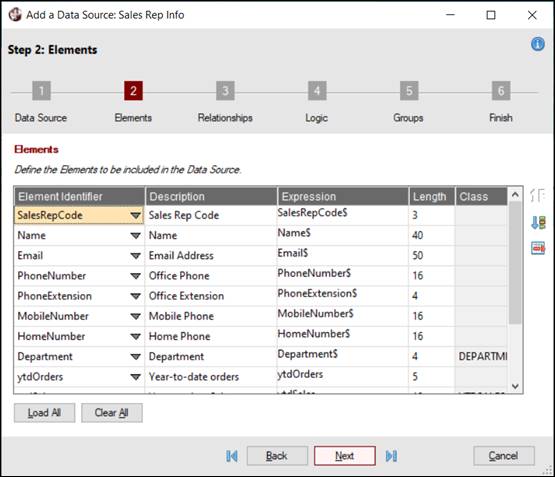
Define the elements (columns) to include in the data source.
This panel consists of the following:
|
Elements |
Each data source contains a list of selected elements (or columns). Elements represent true data fields from the source file or data that is derived from it (e.g. computational results). Anything that can be defined as an expression within PxPlus can become an element. The definition of an element includes a user-friendly description (used in displays), an identifier name (used as a column name for export purposes), and a source expression (used to derive the value). |
|
Element Identifier |
Field or column name for an element (unique within the data source). Click the drop-down to select from a list of existing fields in the data source or enter a new name to create a user-defined element. The new name must begin with an alphabetic character, followed by alphabetic characters (A-Z), digits (0-9) or underscore (_). Maximum 30 characters. |
|
Description |
Description to identify a data element. Maximum 64 characters. If the element comes directly from the primary data source, the description is automatically loaded but can be changed. If creating a user-defined element, enter a description. |
|
Expression |
Expression that will be evaluated to derive the value for an element. Maximum 300 characters. An expression can be a simple variable name or a user-defined formula that uses existing fields in the data source to create a calculated element. For example, a new TotalOrders element may be created by adding two existing fields, ytdOrders+prvOrders. A new PriceDiscount element may be created by multiplying an existing field Price with a fixed numeric value, as in Price*.25. Note:
|
|
Length |
Maximum length of data to be returned for an element. Required for formulas. If empty, the length set in the data dictionary for the element will be used. |
|
Class |
Name of the data class that was set in the data dictionary for an element, if applicable; otherwise, this will be blank and disabled. |
|
Load All |
Loads all file elements for the selected data dictionary file/table into the grid, along with default values for Description, Expression, Length and Class, if applicable. |
|
Clear All |
Clears all file elements from the grid. Prior to clearing the elements, a message will display. |
|
Move Up |
Buttons used to rearrange the order of selected file elements within the grid. |
|
Delete |
Button used to delete a selected file element from the grid. |
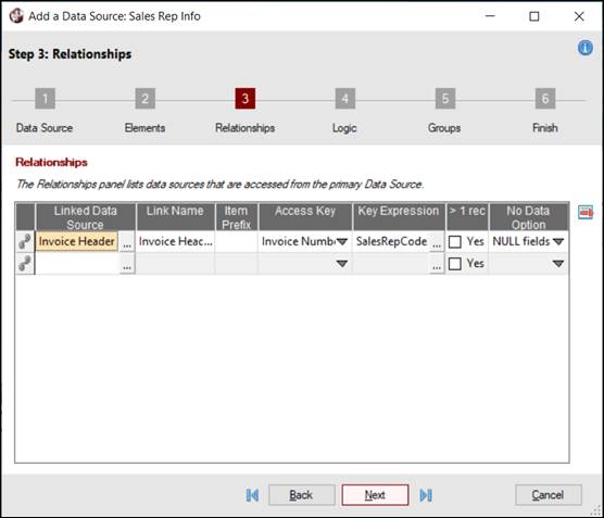
Define any relationship(s) between the primary data source and its related data sources. File link definitions previously created for the primary data source may also be selected, if applicable.
This panel consists of the following:
|
Relationships |
Each data source definition can contain a list of other data sources that may be accessed from its data. These relationships are basically defined by specifying a related data source, its sort key (or index) identifier, and an expression that, when evaluated, provides the range value for reading the key. | ||||||
|
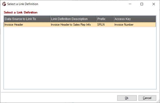
(Select a Link Definition) |
(Available only if file link definitions for the primary data source exist) Button used to invoke the Select a Link Definition window. This window displays only if the primary data source is a data dictionary file/table and file link definitions were previously created in File Link Maintenance. A list of related data sources linked to the data dictionary file/table is displayed. When a link definition is selected, its specifications are used to populate the Relationship entry, which can then be modified if needed. | ||||||
|
Linked Data Source |
Name of a pre-existing data source to be linked with the primary data source (i.e. you must define the data sources to be linked before you can include them as part of a relationship). | ||||||
|
Link Name |
Descriptive relationship name. Loads automatically with the description of the linked data source (but it can be changed). Maximum 64 characters. Must be unique. | ||||||
|
Item Prefix |
Descriptive prefix to be added (optionally) to the related data source element name. Maximum 10 characters. Be aware that when a relationship includes subordinate nested relationships, the prefix cascades down to those relationships as well. This results in compound prefixes for elements in subordinate relationships - a consideration since each prefix becomes part of the column name when selected in a view (and since column names are limited to 60 characters). | ||||||
|
Access Key |
Key (or index) to be used to read the linked data source, selected from the drop box. | ||||||
|
Key Expression |
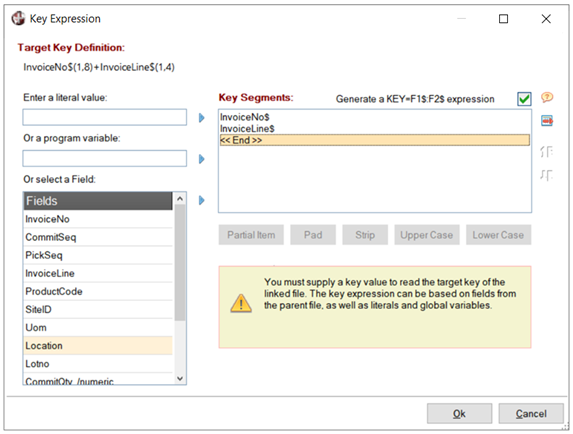
PxPlus expression consisting of fields from the primary data source whose values are used to build the key value for reading the linked data source. A key expression may be string or numeric. Maximum 300 characters. If the names of the fields that make up the link key are the same as the primary data source elements used to create the key expression, then a partial key expression will be generated automatically. Examples: TRN_CUSTID$ "D"+FLD#2$(1,3) PAD(Company$,5,$00$)+PAD(Department$,10,$00$)+STR(EmployeeNum) KEY(__fileFN,KNO=0,KEY=Company$:Department$:EmployeeNum) When dealing with multi-segmented keys (i.e. keys made up of more than one field), you can use a + (plus sign) to concatenate multiple string segments of a key when entering a free-form expression. Be sure to add the correct padding logic to the initial key segments. By default, the initial segments of native PxPlus keys are padded with $00$ characters, and the final segment is not padded. Such a key definition might look like this: PAD(Company$,5,$00$)+PAD(Department$,10,$00$)+STR(EmployeeNum) Individual applications can pad key segments with other characters, such as spaces; therefore, knowledge of the key architecture of individual files is a must. In addition, partial expressions can be entered to define the beginning of the key value in a one-to-many scenario. Knowledge of segment characteristics is not necessary; however, if the key expression uses the KEY(__linkFN,KNO=n,KEY=FLD1$:FLD2$) format where __linkFN is a special channel variable used by the system when evaluating the key, n is the key number used by the file, and FLD1$:FLD2$ are the key segment variables. The latter format is also more flexible as it can handle changes in key segment length if keys are updated for a file. In addition, this format allows a mixture of string and numeric segments. An easy way to build a key expression is to use the key builder utility. This is invoked by clicking the dotted button in the cell associated with this option. The key expression is built by specifying key segments to match the target key definition. These segments can consist of fields from the parent file, literal values and variables. Partial items can be defined, and segments can be padded, have characters stripped, or be converted to upper/lower case. In the case of multi-segment keys, a Generate a KEY=F1$:F2$ expression check box option is available:
Simple numeric keys can be built using a numeric field. Multi-segment numeric keys should be built using the Generate a KEY=F1$:F2$ expression option. (The Generate a KEY=F1$:F2$ expression check box was added in PxPlus 2023.) | ||||||
|
>1 rec |
Check box indicating the correspondence between records returned by a linked data source per record read from the primary data source. When selected, this check box represents one-to-many - there can be many corresponding records in the linked file. This is accomplished using a partial key in the key expression or if there are duplicate keys in the link file. By default, this check box is not selected, indicating a one-to-one correspondence - the value of the key expression matches the key of the linked data source. Only one relationship can be defined as one-to-many for any data source. These may be nested - the data source definition for a one-to-many relationship may itself contain a link for another one-to-many relationship. In this case, all relationships above must be defined as one-to-many. | ||||||
|
No Data Option |
Options for no key match in the linked file:
|
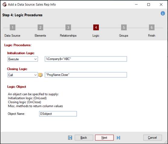
Specify logic to be performed in the data source definition. See Logic Procedures.
This panel consists of the following:
|
Logic Procedures |
Specify initialization and closing logic. A Logic Object can also be specified to supply initialization and closing logic. |
|
Initialization Logic |
Specify initialization logic to be performed. |
|
Closing Logic |
Specify closing logic to be performed. |
|
Logic Object |
Specify an object to supply initialization and closing logic. |
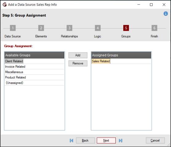
Assign the data source definition to an existing group.
This panel consists of the following:
|
Group Assignment |
A group is a way to organize and relate the data sources logically. Groupings are typically based upon a user view of the data rather than on a physical or application view. |
|
Available Groups |
List box that displays all the existing groups to which the data source definition may be assigned. |
|
Assigned Groups |
List box that is used to show which groups in the Available Groups list have been selected for assigning the new data source to. |
|
Add |
Adds a group selected from the Available Groups list to the Assigned Groups list. |
|
Remove |
Removes a selected group from the Assigned Groups list and returns it to the Available Groups list. |
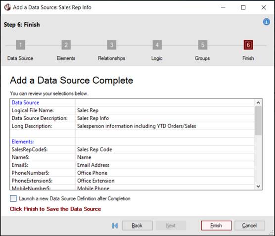
Review the selections for the previous steps, which are presented in a grid format with a vertical scroll bar.
This panel consists of the following:
|
Launch a new Data Source Definition after Completion |
Select this check box to keep the wizard open to define a new data source after clicking the Finish button. If this check box is not selected (default), the wizard will close after clicking the Finish button. |
|
Finish |
Button used to complete the wizard and save the data source definition. If no elements were selected in Step 2: Elements, a message will display. Responding Yes invokes the Step 2: Elements panel so that elements can be selected. (When done, click the Finish button to save.) Responding No saves the data source definition without any elements. |
After the wizard is completed, the data source definition can be recalled in Data Source Maintenance and updated as needed.